MS Equal angle CG center dimension PDF chart | Angle CG center line marking
MS equal angle CG center dimension chart
MS steel equal angle CG center dimension PDF chart
MS equal angle CG Centre dimension table chart
MS equal angle CG center line marking
MS plate to angle fitting with CG Centre line
how to draw CG Centre line of MS angle
how to find any size MS angle CG Centre dimension
माइल्ड स्टील इक्वल एंगल सीजी सेंटर लाइन मार्किंग करें यह पीडीएफ चार्ट के जरिए
किसी भी साइज का एंगल हो उसका सीजी सेंटर पटक कर सकते हैं या पीडीएफ चार्ट के जरिए
एंगल के ऊपर सीजी सेंटर लाइन मार्किंग कैसे करते हैं
सीजी सेंटर लाइन मार्किंग कर के एंगल टू प्लेट फिटिंग कैसे करते हैं
Mild Steel Equal Angle CG Center Line Marking can be done using PDF Chart
Any size of angle can have its CG center marked using PDF Chart
How to do CG center line marking on angle
How to do angle to plate fitting after doing CG center line marking
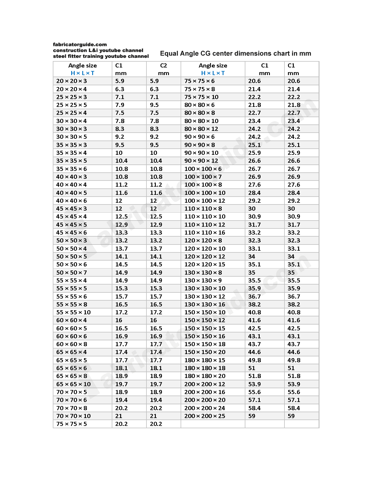
यह चार्ट में इक्वल एंगल का डाइमेंशन दिया गया है और उसका सीजी सेंटर डाइमेंशन दिया गया है
This chart gives the dimensions of equal angle and its CG center dimension
H × L – equal angle web dimension in mm
T – equal angle web thickness in mm dimension
C1 – C2 equal angle CG center dimension in mm

एंगल के चित्र पर जो L और H लिखा गया है वह एंगल का डाइमेंशन है
और जो C1 और C2 जो लिखा गया है वह एंगल का सीजी सेंटर डाइमेंशन है
The letters L and H written on the drawing of an angle are the dimensions of the angle
And the letters C1 and C2 written on the drawing are the CG center dimensions of the angle

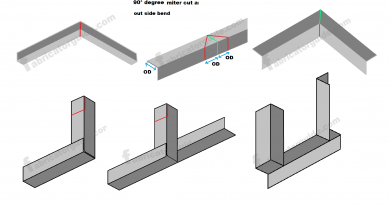
एंगल के ऊपर इस तरह सीजी सेंटर लाइन मार्किंग करें
Do CG center line marking on top of the angle like this

प्लेट के साथ एंगल फिटिंग करने के लिए प्लेट के ऊपर इस तरह सेंटर लाइन मार्किंग करें
To do angle fitting with the plate, mark the center line on the plate like this

इस तरफ प्लेट और एंगल के ऊपर मार्किंग करने के बाद दोनों का सेंटर लाइन इस तरह मिले जैसे चित्र में दिखाया गया है
एंगल को सीजी सेंटर लाइन मार्किंग करके इसलिए फिटिंग किया जाता है ताकि एंगल का लोड कैपेसिटी बढ़ जाए
After marking on this side on the plate and angle, the center line of both should meet as shown in the picture
The angle is fitted by marking the CG center line so that the load capacity of the angle increases

For more information please visit our Youtube channel
Steel Fitter Training Channel
https://www.youtube.com/watch?v=VgsizwDVzWk&t=3s
- 1 cut miter elbow pdf chart
- 45° elbow miter cut pdf chart
- 60° elbow miter cut pdf chart
- 90° elbow miter cut PDF chart
- 90° elbow miter cut PDF chart 2
- 90° Pipe branch reinforcing Pad charts'
- angel CG center dimension chart
- Branch hole marking all
- Elbow dummy support formula
- Elbow miter cut formula
- Fitter book
- Pipe branch elbow dummy pdf chart
- Pipe fitter fabricator interview Q/A 3
- pipe fitter formula 1
- pipe fitter formula 2
- pipe fitter formula 3
- Pipe fitter formula 4
- Pipe fitter formula 5
- Pipe fitter formula 6
- pipe fitter training 1
- pipe fitter training 2
- Pipe fitting's dimension chart 1
- Pipe fitting's dimension chart 2
- pipe schedule PDF chart
- Pipe support
- Pipe to Elbow Straight Branch charts
- piping job interview Q/A 1
- piping job interview Q/A 2
- structure fitter training 1
- structure fitter training 2
- Uncategorized
- Vertical elbow dummy support chart 1
- Vertical elbow dummy support chart 2
- Vertical elbow dummy support chart 3
- Y pipe branch pdf chart